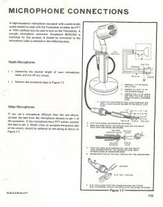

The lines between the symbols represent the electrical connections between components, so users need to make sure they are tracing the correct route. Once all of the symbols and labels have been identified, it's time to study the actual wiring. Additionally, some diagrams have arrows pointing to connections, which denote the direction of the audio signal flow. Each symbol represents a specific component, such as a microphone, amplifier or speaker. There are several basic symbols that are commonly used, such as circles, squares and rectangles. In order to read a Turner microphone wiring diagram, a user must understand the various symbols and labels used to denote each component. Reading Turner Microphone Wiring Diagrams This makes it easier for technicians to determine whether a particular component is malfunctioning or not. By looking at the wiring diagram, it is possible to quickly identify which components are connected, what type of cable is being used and how the audio signal is travelling from one component to the next.
Turner microphone wiring diagrams professional#
However, the diagrams are most often used to show the wiring of a system built around a professional sound board or mixer.

Turner diagrams can be used to represent any type of audio system, such as one built using a turner microphone. The symbols on the diagram help to identify each component and the lines between them denote the electrical connection of each component.
Turner microphone wiring diagrams series#
These diagrams usually feature a series of symbols and labels that indicate each component's physical location, along with a schematic diagram that shows the actual configuration of the components. What Is A Turner Microphone Wiring Diagram?Ī Turner microphone wiring diagram is a visual representation of the electrical connection between components in an audio system. With the help of this article, users can gain a better understanding of how the diagrams work and learn some tips for making their own diagrams to suit their specific needs. The intricacies of Turner microphone wiring diagrams can appear daunting at first, but with a bit of practice, it is possible to become quite proficient at reading them. By taking the time to understand how different components interact, users can better understand the nuances of their systems and be better prepared for any issue that may arise. The diagrams allow technicians to quickly identify where a potential problem lies and make necessary repairs or adjustments to ensure optimal performance. They provide a simplified visual representation of the components, connections and wiring of an audio system. Turner microphone wiring diagrams are essential tools for anyone installing or troubleshooting audio equipment.

Understanding Turner Microphone Wiring Diagrams


 0 kommentar(er)
